Author: Rick Tonoli

  • Car Pi (hardware)

    To keep the post (reasonably) short I’ll break it into 2 pieces, mostly hardware related and mostly software related, and apologies for lack of additional pictures, will add them when I pull the unit out to work on it again (probably this weekend)

    The idea of having a touch screen in your car has always been high on my tech bucket list. Also, I love to build stuff, I like the idea of taking pieces of tech and strapping them together to make something that’s more than the sum of it’s parts, and learning something in the process. I also have a constrained budget, I like to reuse and recycle parts as much as possible.

    So to start, here’s my list of parts (and reasoning):

    A Raspberry Pi 3 B+, I wanted the on board wireless to eliminate an additional USB dongle, and the Bluetooth for later projects.

    A Raspberry Pi 7″ Touchscreen, I had used this as a wall mounted dashboard for my home automation project, but wasn’t really used so purposed it for this.

    A HiFiberry DAC+ Pi HAT, the audio from the Pi is not known for it’s awesomeness, wanted a Pi HAT to solve this and give me RCA audio out.

    The PiJuice HAT, for … reasons:

    • Remove any possibility of the unit draining the car’s battery while giving me the ability to gracefully shutdown the Pi. Yes, I’m aware there are other options I could use by using a combination of the ignition and constant power from battery, but that would involve using the Pi’s GPIO ports and no solution I could think of would absolutely guarantee no parasitic battery drain, except complete isolation.
    • I liked the “smarts” of the PiJuice, essentially it was not just a battery but a battery that gave you hook points into the various states the battery could be in (charging, not charging, battery level etc.), and then allowing you to respond accordingly (there’s more to it than this, but this was enough)
    • The battery was large enough (in theory) to keep the Pi running for a while, particularly if I wanted to have it synchronize with my home network when in range and allow me to remotely do things on it. Plus, if I wanted to I could put a larger battery in.

    A 2 channel amp to power the speakers, I was not looking for epic sound here, just to re purpose the existing front speakers for acceptable sound for music / podcasts / navigation. I went with a cheap one I had lying around, I think I picked up from AliExpress, labelled “500W” but actually more like 20w per channel if you’re lucky. Still, did the job.

    A USB sound card, but only for the mic in part, not the audio out. I needed this for the hands free / speech to text of Android Auto. I originally thought the phone would act as the input but it doesn’t, the unit needs an audio in.

    A ground loop isolator (RCA version) to eliminate the inevitable grounding issues.

    A line level control (attenuator), with RCA in/out to allow externalized volume control. After stripping the plastic casing off this (so it would fit) I realized I paid a bit much for what was just a rotary switch with RCA cables attached, could’ve probably built this myself. And so we learn…

    A lapel microphone to hook into the USB sound card, for audio in. Find something with a long enough cable so you can mount it somehow close to your head. Depending on how much background noise you have you may find it challenging using the voice commands.

    An adapter radio wiring harness for my car. I had no intention of making this a wire splicing hack job into the car. I wanted to be able to plug into the existing radio harness and have it easily removable again. This was hard to find, I ended up finding a generic one for mounting a 3rd party radio to the car and modding it. The one I found was awesome because the wires were labelled (speakers, ground, constant power, ignition power), making the wiring to my unit easy.

    Wire-in Adaptor 12V to 5V USB Micro/Mini for powering the PiJuice (and from that the Pi, DAC and screen). I thought of using one of the many buck converters I had but none of them were as neat as this solution was.

    A type a male to female USB cable, needed this because the Android Auto implementation I used needed the phone wired into a USB port to work. It has a wireless option but I didn’t like it, hopefully it improves. Also, having an external USB port into the Pi is useful for future use (like dropping in a USB radio tuner should I get bored of the Android Auto)

    A replacement fascia for my car that would expose a double din bay. As luck would have it AliExpress had one, once I could figure out what to search for, not knowing it was called a “fascia”.

    A tactile switch, needed to externalize the override kill switch for the PiJuice outside of the dash internals. Important if everything is “hanging” and you’re not keen on the battery draining before it turns off.

    I believe that was the entire parts list.

    As for the assembly, once the radio had been removed and fascia swapped out:

    1. Soldered the external kill switch to the PiJuice on a rather long cable.
    2. Stacked the Pi, Pi Screen, PiJuice and DAC HAT’s together.
    3. Fitted the amp to the cage (it’s a small amp), connected the two USB cables (sound card for audio in and USB extension cable) and connected the lapel mic.
    4. Powered the PiScreen from the Pi, the Pi from the PiJuice, and the PiJuice from the car (via the 12v > 5v converter). The amp is powered directly from the car’s “ignition on” power.
    5. For the audio out: DAC > Volume Control > Ground Loop Isolator > Amp > Car (via harness)
    6. Fitted all of this into the cage as neat as I could (probably could be neater, maybe in version 2).
    7. Raised the screen exactly 1cm above the cage to be flush with the fascia.
    8. Ran the USB cable out the bottom of the dash allowing you to plug a phone in via cable.
    9. For the volume control and kill switch, drilled two tiny holes under the dash in an out of sight, but well within reach area, and mounted them there.

    Bolted the cage back in and reassembled the car fascia and done.

    More in the second post on the software (coming soon) …
  • Dual relay control over WiFi for $6 ?

    I’m a great fan of the ESP8266 boards, having several running with various sensors. I also enjoy the idea of home automation but have never liked the idea of paying so much for the off the shelf hardware. That all changes when I found this:

    Wifi IoT Relay Board Based on ESP8266

    You can read the spec yourself but in a nutshell it exposes 2 relay points you can wire two devices into, taking in mains power and outputting it when the relays are activated.

    My only problem with the device is the build in firmware and accompanying Android app is all in Chinese (or a rather badly translated English).

    Long story short I managed to get this to work with the aRest library (http://arest.io) using an FTDI programmer and Arduino (1.6.8) and this is a quick post to let other people know how I did it (because I couldn’t find anything to help me, maybe I can help others).

    1. The device exposes numerous pins, the pin layout is printed on the underside of the board. You want to wire the FTDI like this: TX <> RX, RX <> TX. Power the board separately off 5v directly on the 5v/G pins. Wire the Ground of the FTDI to the Ground powering the board. Now you’re ready to program it.
    2. Fire up Arduino, use this code:

    [c]

    /*
    Simple script exposing relays on WiFi IOT Relay Board sold by ElectroDragon
    */

    // Import required libraries
    #include <ESP8266WiFi.h>
    #include <aREST.h>

    // Create aREST instance
    aREST rest = aREST();

    // WiFi parameters
    const char* ssid = “<ssid>”;
    const char* password = “<pwd>”;

    // The port to listen for incoming TCP connections
    #define LISTEN_PORT 80

    // Temperature Pins
    #define RELAY_1 13
    #define RELAY_2 12

    // Create an instance of the server
    WiFiServer server(LISTEN_PORT);

    // Variables to be exposed to the API
    float result = 0;

    void setup(void)
    {
    //Start Serial
    Serial.begin(115200);
    pinMode(RELAY_1, OUTPUT);
    pinMode(RELAY_2, OUTPUT);
    // Init variables and expose them to REST API

    // Give name and ID to device
    rest.set_id(“relay”);
    rest.set_name(“relay”);

    // Connect to WiFi
    WiFi.begin(ssid, password);
    while (WiFi.status() != WL_CONNECTED) {
    delay(500);
    Serial.print(“.”);
    }
    Serial.println(“”);
    Serial.println(“WiFi connected”);

    // Start the server
    server.begin();
    Serial.println(“Server started”);

    // Print the IP address
    Serial.println(WiFi.localIP());
    }

    void loop() {

    // Handle REST calls
    WiFiClient client = server.available();
    if (!client) {
    delay(200);
    return;
    }
    while (!client.available()) {
    delay(1);
    }
    rest.handle(client);

    }

    [/c]


    • Next, make sure your copy of Arduino is capable of burning to ESP boards, look at these instructions: https://github.com/esp8266/Arduino
    • Make sure you have the aRest libraries (see https://github.com/marcoschwartz/aREST) and the ESP8266WiFi libraries (see https://github.com/ekstrand/ESP8266wifi)
    • Before burning the firmware, on the board you’ll notice 2 switches below the relays, you need to use BTN2 to put the board into the correct mode to accept the new firmware by unplugging power, pushing and holding in BTN2, repowering the device and letting BTN2 go , see instructions here: http://www.electrodragon.com/w/ESP_Relay_Board.
    • Burn the firmware from Arduino, use the board starting with NodeMCU 0.9…..
    • Once it’s written, you should be able to pick up the board on your network and access the pins to toggle them with http://ip/digital/<pin>/<1 or 0> eg. http://192.168.1.42/digital/13/1 turns on relay on pin 13

    That’s it, dual relays over wifi for $6

    Please note I take no responsibility with what you do with this device, mains power should always be respected. I haven’t actually USED this device other than to get it powered (from mains) and switching the relay, so I know it works. The one thing that concerns me is the lack of earthing wire, and I’m not sure if that’s an issue, someone more knowledgeable should answer that (hint hint)

  • Solving the problem of forgetting to take back library books, and having fun doing it…

    Problem

    With access to 4 library cards, each with 30 book capacity, that’s a whopping 120 books we can take out. The current “reminder” system from our local library involves emailing you 2 days before it’s due, and then 1 week AFTER it’s due (and you’ve picked up fines). We’re currently sitting at around $20 worth of fines and that’s not good at all.

    Solution

    Throw technology at the problem!

    I built an end to end system using a Python, NodeJS and PushBullet. Allowing me to…

    • access a RESTful service to get info on current taken out books, per library card and…
    • send notifications as books approach due date.

    Here’s how I did it:

    1. Scrape web site for data, using Python with HTMLParser to log in and extract the latest book data from the website, dumping it as a JSON string.
    2. Create a NodeJS service to wrap the Python data request and expose it as a RESTful service.

    Tada… now we get notified via PushBullet (https://www.pushbullet.com/) whenever books are about to become due.

    Code available on GitHub

    Remember, it ain’t pretty, but it works 🙂

  • Pi in a box

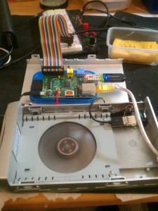
    I’ve had this long running obsession to create a neat enclosure for the Raspberry Pi’s I have, mainly because they lie around all over the place. My first attempt involved using an old drive case (with built in fan) that ended up looking something like this (open):

    Pi in a case

    Which worked pretty well, but then I then decided I wanted EVERYTHING boxed. This would mean I would have to enclose two Pi’s, a drive, a USB hub, and a network switch of some kind (I don’t like wireless for the Pi’s).

    In the end I wanted something I could plug a single network cable and a single power cable in to, that would replace my existing web of cables. I was also constrained by money so this had to be something I could cobble together relatively cheaply.

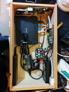
    Long story short, I’ve ended up with this:

    Pi's in a box


    which is still a work in progress, but close to what I want.

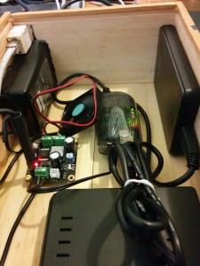
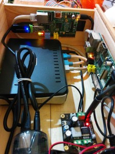
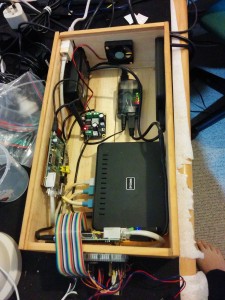
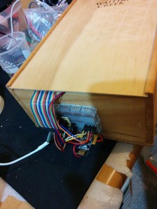
    The container is an old wooden wine box (slide in lid not shown, cost: $2). The router is an old DLINK Wireless Router (free), 2 Raspberry Pi’s (model B) screw mounted into the sides of the box (had these already), a USB hub (to power the drive, also free), an old power supply (not even sure where I got this originally, was lying in a box, so free), a female to female network adapter ($1), a DC-DC converter ($12, I splurged on this for obvious reasons), a 1TB HDD (had this already), a 12V fan (free) and lots of cabling (which I custom made to the right length). So cost wide I’m out less than $20, which wasn’t too bad.

    The power supply is rated at 12V, 5A (60W), the DC-DC converter drops it to 5V, 5A (25W) and this supplies everything with power (I made sure everything ran 5V). The converter came with 3 outputs (conveniently) and a power switch, a perfect fit for what I wanted to do.

    I’ve just built this so whether it’s stable or not is still to be determined. I know Pi’s have issues with power supply so for the next few days I’ll trial this to see if it’s stable. I’m also concerned with the heat inside the box (the Pi’s are running 10 degrees warmer than usual) hence I’m testing the attached fan to see if it remains stable with it running, if so I’ll mount it as an extractor fan, which should help with the heat. I also need to either get or make a shorter USB Type A-B cable for the USB hub to Pi connection, trying to find one but will probably end up “making” one. I then also need to clean up the “hole” I made for the power supply and network point, looks messy at the moment. Finally I’ll need to mount the breakout breadboard I use for accessing the GPIO ports on the Pi, I’ll probably end up attaching that to the lid with a detachable cable.

    In the end I was quite pleased with how it ended up, a bit to do still but I like what’s been done so far. Of course I now need to worry where the NEXT Pi will go, when it arrives 🙂

    Some more pics (more available here):

    2014-09-02 22.52.312014-09-02 22.52.24


    Update: I’ve mounted the fan and added a custom (shorter) USB cable. I think I’m pretty much done for now other than pimping the box with decals (and cleaning up the hole I made 🙂 ). Here are updated pics, with the breakout breadboard mounted on the side of the box.

    2014-09-03 22.56.40 2014-09-03 23.00.41


    Update: Almost 2 months after I posted this and it’s running super stable. I think I rebooted one of the Pi’s twice in all that time. I’ve since upgraded the SD cards to a (hopefully) more stable brand, and swapped out the fan for a 12V PC fan. The Pi’s now run at a cool 36-40 degrees constantly, even under load. I might experiment with over-clocking…

  • Passwordless SSH between two machines using certificates

    I’ve been meaning to post this somewhere useful for a while now, so here it is.

    Assumption

    Machine A wants to connect with SSH without passwords (with cert) to Machine B

    Method

    On Machine A:

    [bash]
    ssh-keygen

    [/bash]

    Make sure you pick no pass phrase.

    [bash]
    scp .ssh/id_rsa.pub user@machineb:.ssh/id_rsa.tmp

    [/bash]

    On Machine B:

    [bash]

    cat id_rsa.tmp >> authorized_keys
    chmod 600 authorized_keys

    [/bash]

    Connect as normal from machine A to machine B
  • Unable to browse network shares on Windows 8

    Again a small side note for anyone experiencing this problem, accessing network shares on windows 8 with elevated privileges seems to be disabled in Windows 8 (not sure about 8.1?), to get around this problem make the following registry changes:

    1. Locate HKEY_LOCAL_MACHINE/SOFTWARE/Microsoft/Windows/CurrentVersion/Policies/System
    2. Create a new DWORD entry with the name EnableLinkedConnections and value 1.
    3. Restart your computer

    You should now be able to view the shares.

    QED

  • Errors when running large numbers of unit tests via mstest on a windows server (just a note really)

    This is really just a note for future reference and to help anyone else experiencing this issue:

    C# projects with hundreds of unit tests (more than a thousand or so) having unit tests failing randomly with the following error:

    The system could not find the environment option that was entered

    or

    Not enough storage is available to process this command

    I battled to find the solution but this KB from Microsoft solved the problem:

    http://support.microsoft.com/?scid=kb%3Ben-us%3B285089&x=15&y=11

    Essentially it involved the following (from the article in case the link goes dead at some point):


    The IRPStackSize parameter specifies the number of stack locations in I/O request packets (IRPs) that are used by Windows 2000 Server, by Windows Server 2003, and by Windows XP. You may have to increase this number for certain transports, for media access control (MAC) drivers, or for file system drivers. Each stack uses 36 bytes of memory for each receive buffer. This value is set in the following registry subkey:

    HKEY_LOCAL_MACHINE\SYSTEM\CurrentControlSet\Services\LanmanServer\Parameters

    The default value of the IRPStackSize parameter is 15. The range is from 11 (0xb hexadecimal) through 50 (0x32 hexadecimal).

    If the subkey is not present, you can use Registry Editor to add the subkey. To do this, follow these steps:

    1. Click Start, click Run, type regedit, and then click OK.
    2. Locate and then click the following registry subkey:
    3. HKEY_LOCAL_MACHINE\SYSTEM\CurrentControlSet\Services\LanmanServer\Parameters
    4. Click Edit, point to New, and then click DWORD Value.
    5. Type IRPStackSize, and then press ENTER to name the value.Note Type IRPStackSize exactly as it is displayed. The value name is case sensitive.
    6. Click Edit, and then click Modify.
    7. In the Data Value box, type the value that is appropriate for the network, and then click OK.


    Hope this proves useful to someone in the future, sure took me a long time to find the solution.

  • Accuracy and Precision

    Today I got asked what I thought was the difference between accuracy and precision as it pertains to relative estimation, I wasn’t ready for the question though and it’s been sitting on my mind bugging me so here are my thoughts:

    I would think accuracy would be how close the estimation was to the truth and precision is how often you predict the same estimation given the same or similar complexity, in other words how repeatable you are. Accuracy is how right or wrong you are and precision is about how consistent you are (irrespective of right or wrong).

    So, if you correctly estimate over and over, you’d be accurate and precise but if you estimate incorrectly, but are consistent about the “incorrectness” then you would be precise but not accurate. If you estimate correctly only every now and then for the same given complexity then you would be accurate but lack precision.

    Interesting to hear what others think (like if I’ve lost my mind completely 🙂 )…


  • Continuous Improvement

    Thinking about continuous improvement the other day I tried to figure out what makes a continuous improvement process work and what makes it stick, these are my thoughts:

    • It should be a slow, gradual process of change, no “sudden movements”.
    • It should be a continuous flow of change, no settling down into a rut.
    • It should be a culture, not a bunch of individuals with ideas.
    • It should be unanimously accepted.
    • It should be measurable.
    • It should be celebrated.
    • It should be evangelized.
    • There should be room for failure, and for success.
    • It should be rewarded.
    • It should be encouraged.
    • It should become default behaviour.
    • It should be transparent.

    What else?


  • Emailing attachments directly to a Dropbox folder…

    I’ve been toying with this idea for a while now, wanting to email attachments to my Dropbox account into a specific folder. There are lots of canned solutions to do this, but most of them require you to trust some third party with your documents. If you’re ok with that check out this post.

    I decided my paranoia was high and I would not trust a third party. To achieve autonomous Dropbox emailing I figured I’d need to do the following:

    1. Install Dropbox on my headless Ubuntu server.
    2. Create an email account to receive the email attachments (let’s say dropbox@mydomain.com).
    3. Modify the postfix installation to redirect mail to dropbox@mydomain.com to a PHP script.
    4. Create a PHP script to process the inbound email stream and strip out all attachments saving them to a folder.

    Install Dropbox

    Lots of links for this one out there, not going to rehash it but the basics are:

    1. Download the latest Dropbox.
    2. Run it.
    3. Use the link supplied to link your account to your server.
    4. Create a service to run Dropbox at start.
    5. Do an initial sync.

    You can follow the instructions here, or Google for it.

    Create Email Account

    I created a user called dropbox  and ran the install above as that user. One note if you follow the link, I did not do the auto startup as a cron job but as a standard service in /etc/init.d

    Modify Postfix

    I created a new transport in master.cf:

    [bash]

    dropbox unix – n n – 50 pipe
    flags=R user=dropbox argv=/usr/bin/php /usr/local/bin/dropboxattach/dropbox.php -o SENDER=${sender} -m USER=${user} EXTENSION=${extension}

    [/bash]

    then I added an entry to my main.cf to define different transport options:

    [bash]transport_maps = hash:/etc/postfix/transport[/bash]

    Now edit /etc/postfix/transport and add an entry for your email address receiving the dropbox attachments:

    [bash]dropbox@mydomain.com  dropbox:[/bash]

    then run

    [bash]postmap transport [/bash]

    to (re)build the transport database

    Finally reload postfix

    [bash]postfix reload [/bash]

    The PHP Script

    I found this nifty little Mime Mail Parser script at http://code.google.com/p/php-mime-mail-parser/, download the two files and add it to your code source. Here is the script I created to intercept the mail and parse for attachments. Check comments for explanation.

    [php]

    <?php

    require_once(‘MimeMailParser.class.php’);

    // phrase to check for in SUBJECT to make sure only valid emails are processed
    $check = “Add to dropbox”;

    // location to save attachments to
    $save_dir = “/home/dropbox/Dropbox/attachments”;

    // temporary file name for incoming mail message
    $file = “/tmp/mail.message.” . microtime(true);

    // delete the temp file if it exists, just in case
    if (file_exists($file)) {
    unlink($file);
    }

    // export the mail message to the temporary file
    $data = file_get_contents(“php://stdin”);
    file_put_contents($file, $data);

    // parse the contents of the message and save attachments
    $Parser = new MimeMailParser();
    $Parser->setPath($file);

    // get the subject and check for valid “phrase”
    $subject = $Parser->getHeader(‘subject’);

    if (!($subject == $check)) {
    // delete the temp mail message
    if (file_exists($file)) {
    unlink($file);
    }
    exit();
    }

    // get all attachments and save to directory
    $attachments = $Parser->getAttachments();
    foreach($attachments as $attachment) {
    // get the attachment name
    $filename = $attachment->filename;
    // write the file to the directory you want to save it in
    if ($fp = fopen($save_dir.$filename, ‘w’)) {
    while($bytes = $attachment->read()) {
    fwrite($fp, $bytes);
    }
    fclose($fp);
    }
    }

    // delete the temp file (probably redundant but just in case)
    if (file_exists($file)) {
    unlink($file);
    }

    ?>

    [/php]

    For some “security” I added a “catch phrase” that must be the subject as a kind of “authentication”. Remember to save the script into the same directory as the Mail Parser code and everything should work.

    That was it, I can now email dropbox@mydomain.com and it appears in my dropbox folder Attachments .. AWESOME!