Car Pi (hardware)

To keep the post (reasonably) short I’ll break it into 2 pieces, mostly hardware related and mostly software related, and apologies for lack of additional pictures, will add them when I pull the unit out to work on it again (probably this weekend)

The idea of having a touch screen in your car has always been high on my tech bucket list. Also, I love to build stuff, I like the idea of taking pieces of tech and strapping them together to make something that’s more than the sum of it’s parts, and learning something in the process. I also have a constrained budget, I like to reuse and recycle parts as much as possible.

So to start, here’s my list of parts (and reasoning):

A Raspberry Pi 3 B+, I wanted the on board wireless to eliminate an additional USB dongle, and the Bluetooth for later projects.

A Raspberry Pi 7″ Touchscreen, I had used this as a wall mounted dashboard for my home automation project, but wasn’t really used so purposed it for this.

A HiFiberry DAC+ Pi HAT, the audio from the Pi is not known for it’s awesomeness, wanted a Pi HAT to solve this and give me RCA audio out.

The PiJuice HAT, for … reasons:

  • Remove any possibility of the unit draining the car’s battery while giving me the ability to gracefully shutdown the Pi. Yes, I’m aware there are other options I could use by using a combination of the ignition and constant power from battery, but that would involve using the Pi’s GPIO ports and no solution I could think of would absolutely guarantee no parasitic battery drain, except complete isolation.
  • I liked the “smarts” of the PiJuice, essentially it was not just a battery but a battery that gave you hook points into the various states the battery could be in (charging, not charging, battery level etc.), and then allowing you to respond accordingly (there’s more to it than this, but this was enough)
  • The battery was large enough (in theory) to keep the Pi running for a while, particularly if I wanted to have it synchronize with my home network when in range and allow me to remotely do things on it. Plus, if I wanted to I could put a larger battery in.

A 2 channel amp to power the speakers, I was not looking for epic sound here, just to re purpose the existing front speakers for acceptable sound for music / podcasts / navigation. I went with a cheap one I had lying around, I think I picked up from AliExpress, labelled “500W” but actually more like 20w per channel if you’re lucky. Still, did the job.

A USB sound card, but only for the mic in part, not the audio out. I needed this for the hands free / speech to text of Android Auto. I originally thought the phone would act as the input but it doesn’t, the unit needs an audio in.

A ground loop isolator (RCA version) to eliminate the inevitable grounding issues.

A line level control (attenuator), with RCA in/out to allow externalized volume control. After stripping the plastic casing off this (so it would fit) I realized I paid a bit much for what was just a rotary switch with RCA cables attached, could’ve probably built this myself. And so we learn…

A lapel microphone to hook into the USB sound card, for audio in. Find something with a long enough cable so you can mount it somehow close to your head. Depending on how much background noise you have you may find it challenging using the voice commands.

An adapter radio wiring harness for my car. I had no intention of making this a wire splicing hack job into the car. I wanted to be able to plug into the existing radio harness and have it easily removable again. This was hard to find, I ended up finding a generic one for mounting a 3rd party radio to the car and modding it. The one I found was awesome because the wires were labelled (speakers, ground, constant power, ignition power), making the wiring to my unit easy.

Wire-in Adaptor 12V to 5V USB Micro/Mini for powering the PiJuice (and from that the Pi, DAC and screen). I thought of using one of the many buck converters I had but none of them were as neat as this solution was.

A type a male to female USB cable, needed this because the Android Auto implementation I used needed the phone wired into a USB port to work. It has a wireless option but I didn’t like it, hopefully it improves. Also, having an external USB port into the Pi is useful for future use (like dropping in a USB radio tuner should I get bored of the Android Auto)

A replacement fascia for my car that would expose a double din bay. As luck would have it AliExpress had one, once I could figure out what to search for, not knowing it was called a “fascia”.

A tactile switch, needed to externalize the override kill switch for the PiJuice outside of the dash internals. Important if everything is “hanging” and you’re not keen on the battery draining before it turns off.

I believe that was the entire parts list.

As for the assembly, once the radio had been removed and fascia swapped out:

  1. Soldered the external kill switch to the PiJuice on a rather long cable.
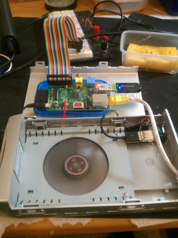
  2. Stacked the Pi, Pi Screen, PiJuice and DAC HAT’s together.
  3. Fitted the amp to the cage (it’s a small amp), connected the two USB cables (sound card for audio in and USB extension cable) and connected the lapel mic.
  4. Powered the PiScreen from the Pi, the Pi from the PiJuice, and the PiJuice from the car (via the 12v > 5v converter). The amp is powered directly from the car’s “ignition on” power.
  5. For the audio out: DAC > Volume Control > Ground Loop Isolator > Amp > Car (via harness)
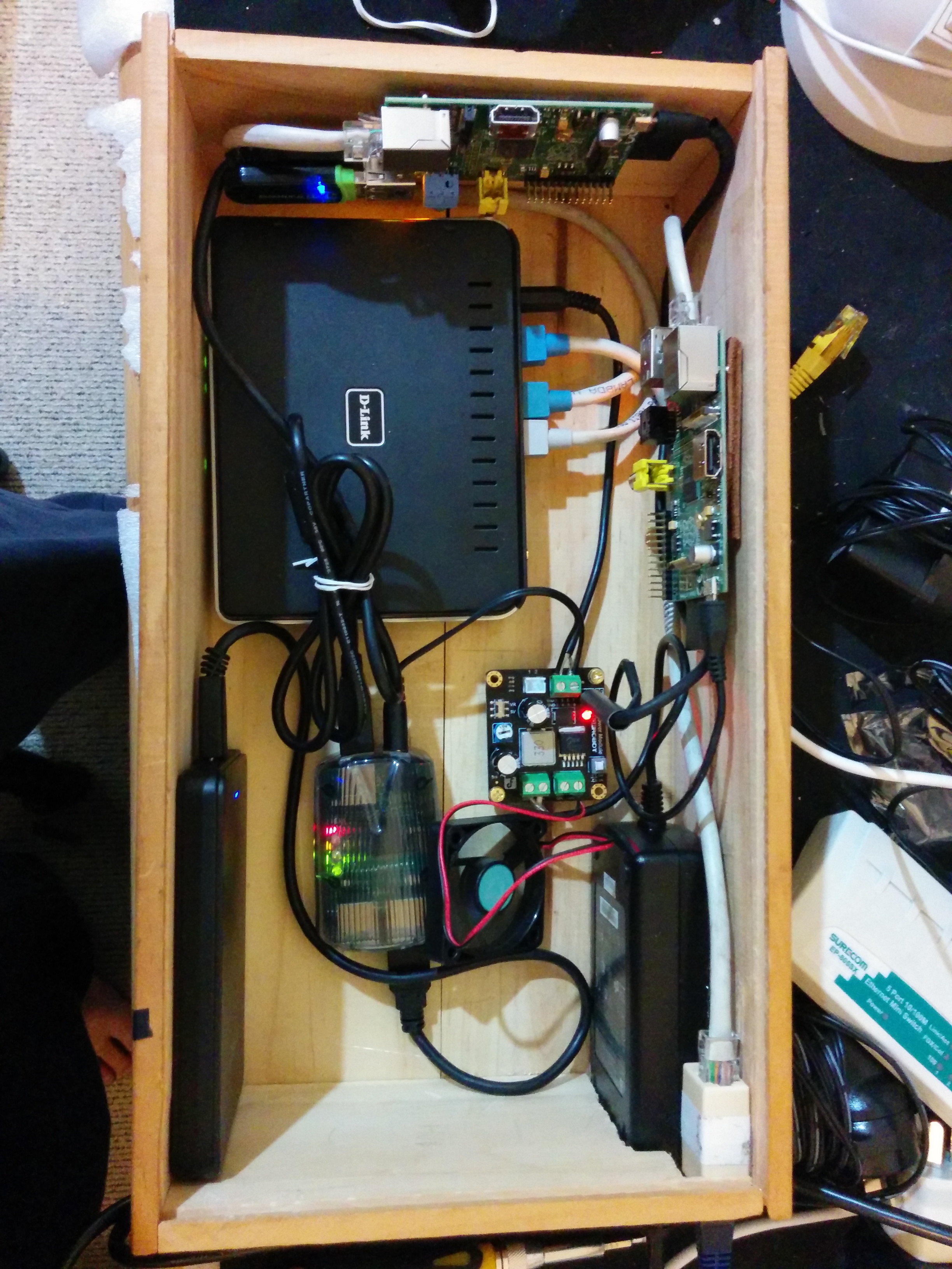
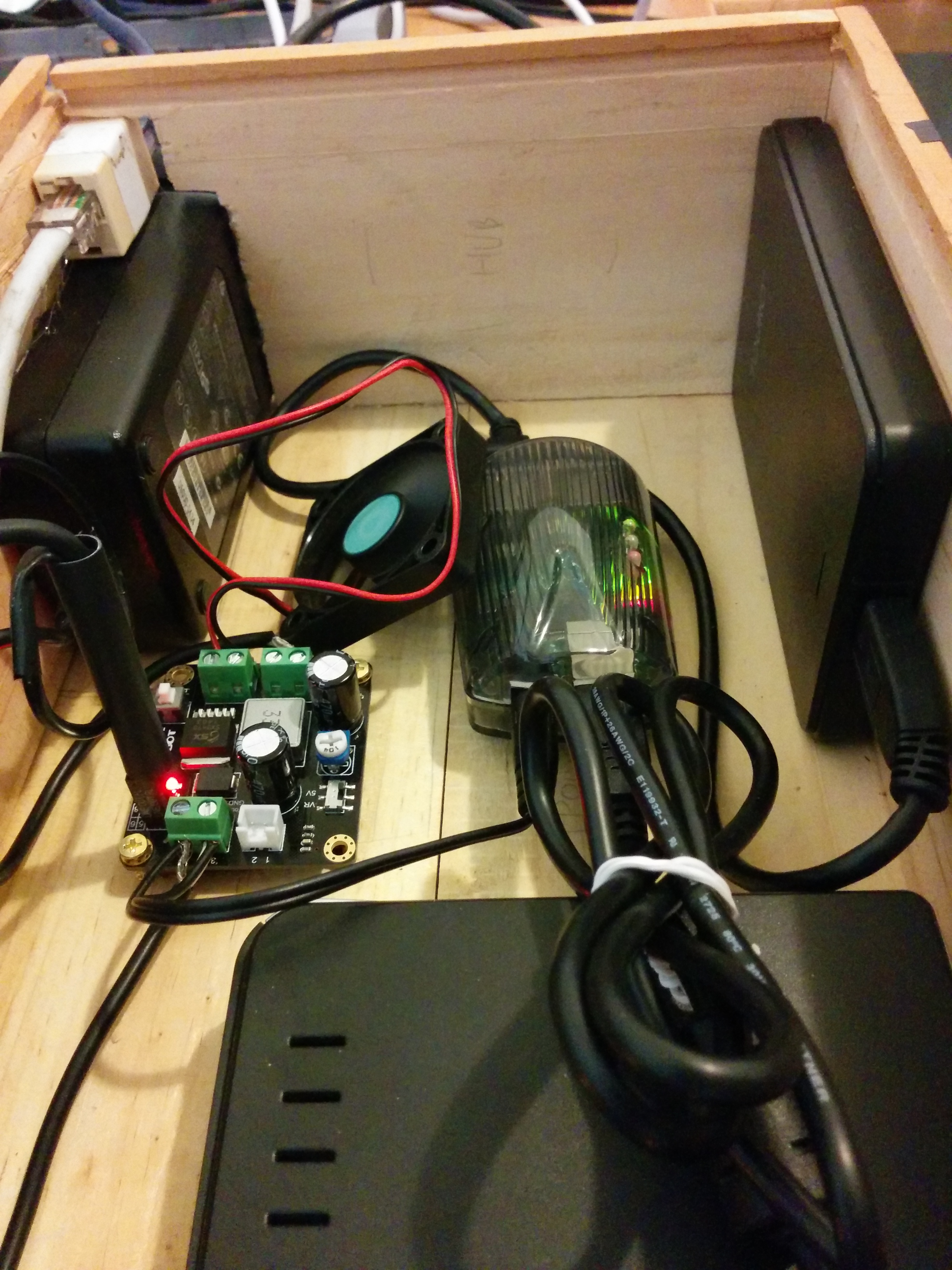
  6. Fitted all of this into the cage as neat as I could (probably could be neater, maybe in version 2).
  7. Raised the screen exactly 1cm above the cage to be flush with the fascia.
  8. Ran the USB cable out the bottom of the dash allowing you to plug a phone in via cable.
  9. For the volume control and kill switch, drilled two tiny holes under the dash in an out of sight, but well within reach area, and mounted them there.

Bolted the cage back in and reassembled the car fascia and done.

More in the second post on the software (coming soon) …

Dual relay control over WiFi for $6 ?

I’m a great fan of the ESP8266 boards, having several running with various sensors. I also enjoy the idea of home automation but have never liked the idea of paying so much for the off the shelf hardware. That all changes when I found this:

Wifi IoT Relay Board Based on ESP8266

You can read the spec yourself but in a nutshell it exposes 2 relay points you can wire two devices into, taking in mains power and outputting it when the relays are activated.

My only problem with the device is the build in firmware and accompanying Android app is all in Chinese (or a rather badly translated English).

Long story short I managed to get this to work with the aRest library (http://arest.io) using an FTDI programmer and Arduino (1.6.8) and this is a quick post to let other people know how I did it (because I couldn’t find anything to help me, maybe I can help others).

  1. The device exposes numerous pins, the pin layout is printed on the underside of the board. You want to wire the FTDI like this: TX <> RX, RX <> TX. Power the board separately off 5v directly on the 5v/G pins. Wire the Ground of the FTDI to the Ground powering the board. Now you’re ready to program it.
  2. Fire up Arduino, use this code:

/*
Simple script exposing relays on WiFi IOT Relay Board sold by ElectroDragon
*/

// Import required libraries
#include <ESP8266WiFi.h>
#include <aREST.h>

// Create aREST instance
aREST rest = aREST();

// WiFi parameters
const char* ssid = "<ssid>";
const char* password = "<pwd>";

// The port to listen for incoming TCP connections
#define LISTEN_PORT 80

// Temperature Pins
#define RELAY_1 13
#define RELAY_2 12

// Create an instance of the server
WiFiServer server(LISTEN_PORT);

// Variables to be exposed to the API
float result = 0;

void setup(void)
{
//Start Serial
Serial.begin(115200);
pinMode(RELAY_1, OUTPUT);
pinMode(RELAY_2, OUTPUT);
// Init variables and expose them to REST API

// Give name and ID to device
rest.set_id("relay");
rest.set_name("relay");

// Connect to WiFi
WiFi.begin(ssid, password);
while (WiFi.status() != WL_CONNECTED) {
delay(500);
Serial.print(".");
}
Serial.println("");
Serial.println("WiFi connected");

// Start the server
server.begin();
Serial.println("Server started");

// Print the IP address
Serial.println(WiFi.localIP());
}

void loop() {

// Handle REST calls
WiFiClient client = server.available();
if (!client) {
delay(200);
return;
}
while (!client.available()) {
delay(1);
}
rest.handle(client);

}


  • Next, make sure your copy of Arduino is capable of burning to ESP boards, look at these instructions: https://github.com/esp8266/Arduino
  • Make sure you have the aRest libraries (see https://github.com/marcoschwartz/aREST) and the ESP8266WiFi libraries (see https://github.com/ekstrand/ESP8266wifi)
  • Before burning the firmware, on the board you’ll notice 2 switches below the relays, you need to use BTN2 to put the board into the correct mode to accept the new firmware by unplugging power, pushing and holding in BTN2, repowering the device and letting BTN2 go , see instructions here: http://www.electrodragon.com/w/ESP_Relay_Board.
  • Burn the firmware from Arduino, use the board starting with NodeMCU 0.9…..
  • Once it’s written, you should be able to pick up the board on your network and access the pins to toggle them with http://ip/digital/<pin>/<1 or 0> eg. http://192.168.1.42/digital/13/1 turns on relay on pin 13

That’s it, dual relays over wifi for $6

Please note I take no responsibility with what you do with this device, mains power should always be respected. I haven’t actually USED this device other than to get it powered (from mains) and switching the relay, so I know it works. The one thing that concerns me is the lack of earthing wire, and I’m not sure if that’s an issue, someone more knowledgeable should answer that (hint hint)

Pi in a box

I’ve had this long running obsession to create a neat enclosure for the Raspberry Pi’s I have, mainly because they lie around all over the place. My first attempt involved using an old drive case (with built in fan) that ended up looking something like this (open):

Pi in a case

Which worked pretty well, but then I then decided I wanted EVERYTHING boxed. This would mean I would have to enclose two Pi’s, a drive, a USB hub, and a network switch of some kind (I don’t like wireless for the Pi’s).

In the end I wanted something I could plug a single network cable and a single power cable in to, that would replace my existing web of cables. I was also constrained by money so this had to be something I could cobble together relatively cheaply.

Long story short, I’ve ended up with this:

Pi's in a box


which is still a work in progress, but close to what I want.

The container is an old wooden wine box (slide in lid not shown, cost: $2). The router is an old DLINK Wireless Router (free), 2 Raspberry Pi’s (model B) screw mounted into the sides of the box (had these already), a USB hub (to power the drive, also free), an old power supply (not even sure where I got this originally, was lying in a box, so free), a female to female network adapter ($1), a DC-DC converter ($12, I splurged on this for obvious reasons), a 1TB HDD (had this already), a 12V fan (free) and lots of cabling (which I custom made to the right length). So cost wide I’m out less than $20, which wasn’t too bad.

The power supply is rated at 12V, 5A (60W), the DC-DC converter drops it to 5V, 5A (25W) and this supplies everything with power (I made sure everything ran 5V). The converter came with 3 outputs (conveniently) and a power switch, a perfect fit for what I wanted to do.

I’ve just built this so whether it’s stable or not is still to be determined. I know Pi’s have issues with power supply so for the next few days I’ll trial this to see if it’s stable. I’m also concerned with the heat inside the box (the Pi’s are running 10 degrees warmer than usual) hence I’m testing the attached fan to see if it remains stable with it running, if so I’ll mount it as an extractor fan, which should help with the heat. I also need to either get or make a shorter USB Type A-B cable for the USB hub to Pi connection, trying to find one but will probably end up “making” one. I then also need to clean up the “hole” I made for the power supply and network point, looks messy at the moment. Finally I’ll need to mount the breakout breadboard I use for accessing the GPIO ports on the Pi, I’ll probably end up attaching that to the lid with a detachable cable.

In the end I was quite pleased with how it ended up, a bit to do still but I like what’s been done so far. Of course I now need to worry where the NEXT Pi will go, when it arrives 🙂

Some more pics (more available here):

2014-09-02 22.52.312014-09-02 22.52.24


Update: I’ve mounted the fan and added a custom (shorter) USB cable. I think I’m pretty much done for now other than pimping the box with decals (and cleaning up the hole I made 🙂 ). Here are updated pics, with the breakout breadboard mounted on the side of the box.

2014-09-03 22.56.40 2014-09-03 23.00.41


Update: Almost 2 months after I posted this and it’s running super stable. I think I rebooted one of the Pi’s twice in all that time. I’ve since upgraded the SD cards to a (hopefully) more stable brand, and swapped out the fan for a 12V PC fan. The Pi’s now run at a cool 36-40 degrees constantly, even under load. I might experiment with over-clocking…